This paper is collaborated between me and my colleague Songyu Yao. This is our literature review of Printed artificial cilia from liquid-crystal network actuators modularly driven by light, which is written by Casper L. van Oosten, Cees W. M. Bastiaansen and Dirk J. Broer on Nature Materials.
Introduction of Basic Concepts
Liquid Crystals
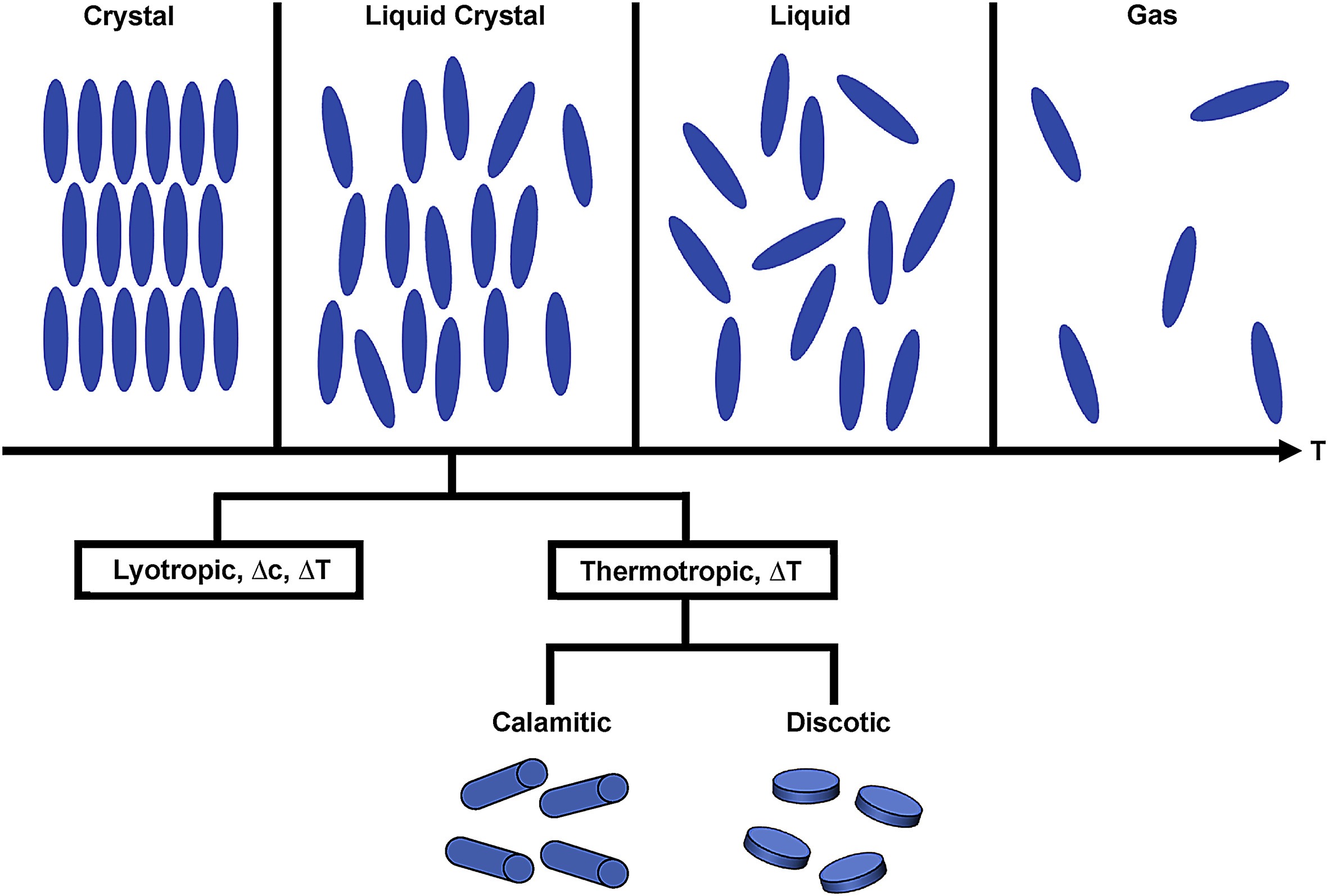
Liquid crystals (LC) are materials with anisotropy, the position of molecules can be randomly arranged, which means it can flow like a liquid, but the molecules are fixed oriented. Typically, liquid crystals are divided into thermotropic, lyotropic and metallotropic.
Liquid crystals have properties like electric properties, elastic properties and optical properties. For example, by varying the temperature of the materials, the phases of thermotropic crystals are changed. Similarly, by changing the conditions like temperature and concentration of molecules in liquids, lyotropic can be formed.
Liquid Crystalline Polymers
Polymers are fantastic materials for micromechanical systems (MEMS) and lab-on-a-chip systems. However, there are still several challenges for large-scale manufacturing. On the one hand, it’s tough to process polymer actuators for microstructuring, which leads to a more complicated production. On the other hand, when the actuators are electrically addressed, production in an extreme manufacturing environment, like high temperature, acid or basic conditions is inevitable.
Liquid crystal polymer is a thermoplastic polymer material with useful physical properties. What it’s different from most polymers is that there are rigid and flexible monomers linking to each other. Thus, if the orientation of the molecules is formed, even if the liquid crystal polymer is cooled down from high temperature, the structure is also unchanged.
Based on the theory that liquid crystal polymer has a reversible structure with electrical, thermal, mechanical and chemical properties, it is an advantaged material to act as a polymer actuator. For the mechanical extension measurement, the stretching leads to a large manufacturing environment which is impossible for a microscale condition, so the strain processing way will not be a solution.
Stimuli-Responsive Liquid Crystal Polymers
Stimuli-responsive polymers are a kind of material that is responsive to physical or chemical conditions of the environment, like temperature, mechanical force, light, PH and electric and magnetic fields. Nowadays, stimuli-responsive polymers play a crucial role in applications like sensing, controlled drug delivery, artificial muscles and actuators.
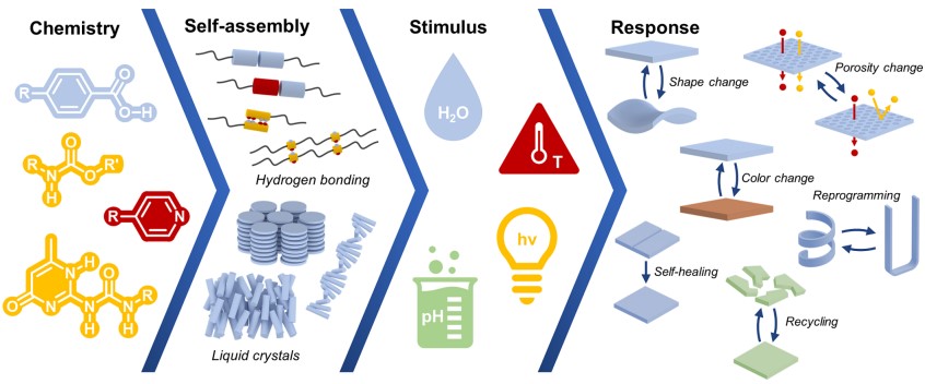
Liquid crystals are attractive for stimuli-responsive polymer materials because of their self-assembly properties. The shape of liquid crystals will change in response to stimuli which we mainly discuss light here. Nowadays, there are a lot of advancements developed in stimuli-responsive liquid crystal polymers such as soft robotics, deployable soft actuating devices, responsive pigments and sensors.
Experimental & Methods Review
In this section, we will talk about the experiment part in the literature, and the methods they used in the study. The researchers used many monomer materials to form photoactive actuators, tried methods to fabricate devices, explained the mechanism of those polymers through the characterization experiment of the microstructure, and demonstrated their responsiveness.
Materials
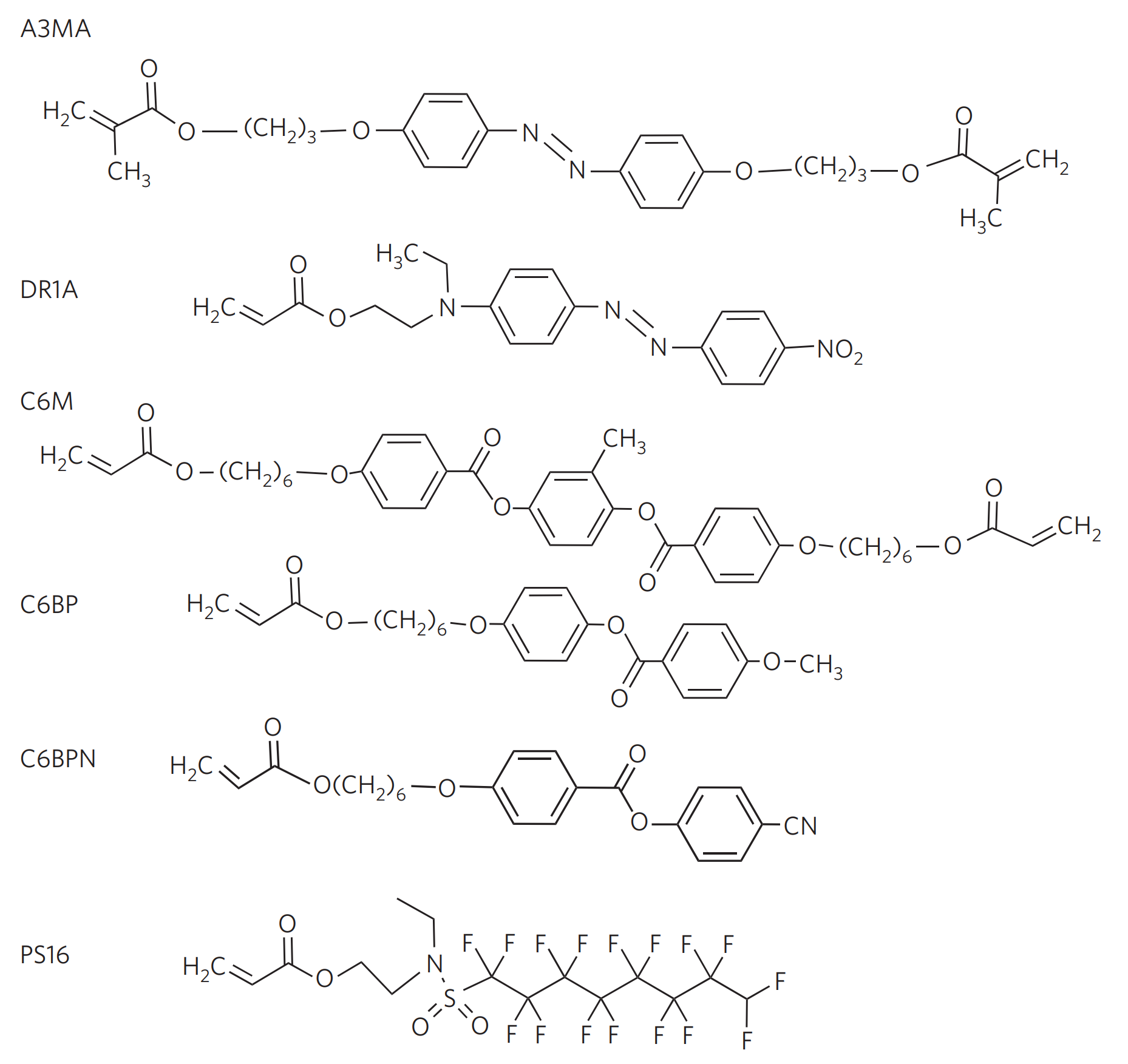
The monomer materials used in this study to form the actuators are C6M, C6BP, C6BPN, A3MA and DR1A, besides, PS16 are also used in the experiment as the surfactant (Fig.3). Among them, A3MA and DR1A are two photoactive monomers, and C6M, C6BP and C6BPN are used to build the host matrix. Then to obtain the desired alignment at the air interface, they used the surfactant PS16 in the study.
Monomers C6M, C6BP and C6BPN should be mixed in the weight ratio 2:3:1, these were provided by Merck. Monomer A3MA was bought from Syncom and DR1A was obtained from Aldrich.
The choice of the concentration of the azobenzene monomers should be careful. It is determined by the extinction length d for non-polarized light at the peak absorption wavelengths of the dye, the measurement in DR1A and A3MA polymer film samples should be made when the samples are in planar uniaxial alignment and with known concentration and thickness. To calculate the extinction length d, the natural base definition of extinction length d as fellow is used: $$ I/I_o = e^{-x/d} $$
The dye concentrations in the final monomeric mixtures were then set to 5.6 µm (DR1A polymer) and 5.75 µm (A3MA polymer), to ensure a deep penetration of light into the 10-µm-thick actuators.
The surfactant PS16, 2-(N-ethyl Perfluorooctane Sulfonamido) ethyl acrylate obtained from Acros was added in 0.5 wt% to the mix, and Irgacure 819 (Ciba) was added in 0.5 wt% as a photoinitiator. At last, the system was dissolved in a 1:1 weight ratio with dichloroethane (Biosolve).
Sample and experiment preparation
All experiments in the study were carried out on glass substrates of 30×30 mm, before using them researchers needed to make sure that they were cleaned in ethanol and dried. The production of the actuator is based on the PVA release layer, which is soluble in water but not in the solvents used for the processing of the polyimide or the liquid-crystal monomers.
Because of the existence of surface free energy, under unforced conditions, the mix of liquid-crystal monomers will minimize its surface free energy, which leads to an alignment perpendicular to the air interface. That’s why researchers added a small amount of surfactant PS16 to overcome it, by adding this to the reactive monomeric mix, they can gain plane alignment at the air interface. And then they give the molecular alignment at the bottom surface a slight pre-tilt from the surface normal, to make sure the directionality of the alignment at the air interface is introduced.
In the specific details of the operation, researchers used spin-coating technology to fabricate the macroscopic system. They first worked on a glass substrate and coated it with polyimide (grade 5300; Nissan Chemicals) to produce the macroscopic flaps.
To obtain the desired pre-tilt, the polyimide should be manually buffed. Then under a spin-coated on at 2,000 r.p.m. for 30 s, the monomeric mix will form a 10-µm-thick monodomain alignment. After spin-coating, the samples should evaporate the solvent, this process will happen at 37 ℃ for 60 s and then they can photopolymerized punder nitrogen blanketing. Finally, strips were cut from the A3MA and DR1A polymer with a razor blade and glued together.
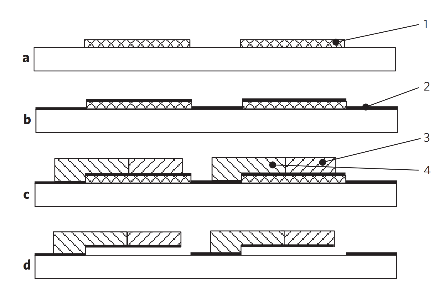
The figure above shows the steps of the most important process to microstructure the actuators. This is the inkjet printing technology, which allows variations of the material composition in the plane of the substrate in a single processing step. Compared to other micropatterning techniques such as lithography which requires many more steps to achieve the same, inkjet printing makes large-scale manufacture possible\cite{liu2021light}. The monomeric liquid-crystal mix containing one of the two dyes was deposited on the substrate, by using a commercial inkjet printer. It takes 4 steps to finish the production of the modular cilia in the study :
- a. Structured deposition of the PVA release layer. Regular PVA cannot be photopatterned directly, the desired structure is obtained by a lift-off process, using the Ma-N 490 photoresist (Microresist) to pattern the negative image.
- b. The second step is about the alignment material, polyimide (grade 5300; Nissan Chemicals)and its spin-coating, curing and buffing of the polyimide alignment layer.
- c. This is the inkjet print key step. Inkjet deposition of the monomer mixes containing DR1A (3) and A3MA (4) and curing. During this step, the samples need to be cured under nitrogen blanketing at 37 ℃ for 5 min. Using visible light for A3MA polymer and ultraviolet light for DR1A polymer to finish the deposition. In this literature, they used a commercial Fuji Dimatix printer to print the monomeric mix. And this nozzle was heated to 50 ℃, which can help to evaporate the solvent and the liquid-crystal monomers self-assembled into the splayed orientation.
- d. Dissolving the sacrificial PVA release layer in water so that the cilia were partially released from the substrate.
Characterization of the microstructures
To analyze the working mechanism of the actuators, their microstructures need to be characterized and studied. In the literature, different methods were used for different structural parameters to get a characterization of those liquid-crystalline units. To measure the height of the microstructures, the researchers used a Fogale Nanotech Zoomsurfer 3D interferometer. Then crossed polarizers to check visually the alignment of the liquid-crystal polymer, and confirmed by using microscopy. For the scanning electron micrographs, they were made on a Philips XL30 FEG ESEM at 10 kV under high vacuum, after coating the sample with a 25 nm gold layer.
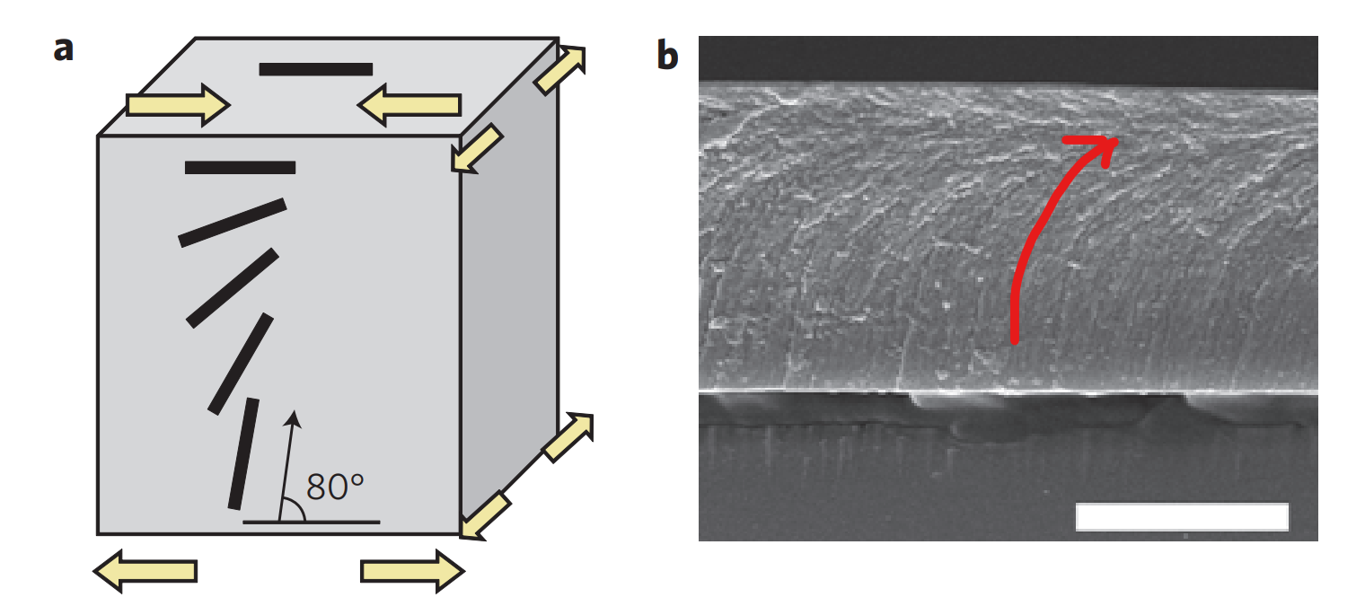
After breaking the sample, inspect the fracture surface by using the scanning electron microscopy method, it’s very easy to observe the visible alignment in Fig.5b. To facilitate understanding, I have drawn schematic arrows on the figure showing the orientation in which the liquid-crystalline units have changed. Its structural features follow schematic the in Fig.5a. It presents a splay–bend configuration, as the thickness of the film changes, the liquid-crystalline units undergo a gradual orientational change from perpendicular to the substrate at the bottom, to parallel at the top, causing the bottom the film to expand and the top to contract. On one hand, that’s why you can see the alignment of the liquid-crystalline formed an arc from bottom to top in Fig.5b. On the other hand, this explains the meaning of the arrows in Fig.5a: the expansion at the bottom of the film and the contract at the top. Both the bending direction and the bend axis of the film are dictated by the splayed molecular alignment, so this structure can make the direction of the response independent from the direction of the incident light. Besides, it can help control the self-assembly of the liquid crystals so that creating an upward-bending (rather than a downward-bending) splayed actuator is possible.
Macrostructure
In this section, we will discuss the macrostructure of the actuator and how it works. The group in the literature is dedicated to producing artificial cilia that are driven by light for use as mixers or pumps in microfluidic systems. The reason why actuators driven by light can help them do that is when the light makes a change, the actuator makes a flapping, asymmetric motion, causing an effective flow in the surrounding fluid, with a backward stroke different from the forward stroke. Liquid-crystal azobenzene is the key to achieving that since the light absorption can change the spacial structure of azobenzene, which in turn leads to macroscopic deformations. However, a single dye makes it difficult to initiate large deformations as the actuator has small dimensions. That’s why two dyes were introduced by the study group.
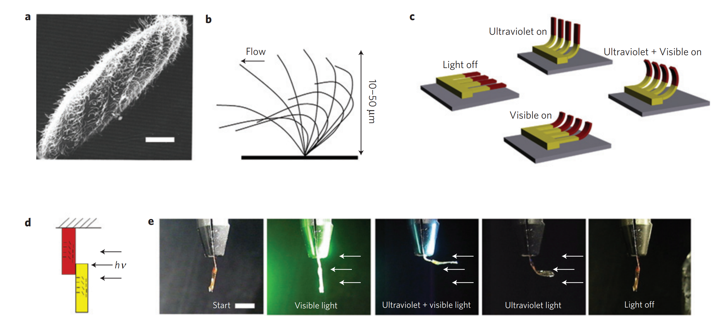
The actuator has the structure shown in Fig.6d. The yellow part is the A3MA dyed polymer part mounted at the bottom, while the red part is the DR1A polymer part mounted at the top. Different peak absorption wavelength of light makes it form 4 positions work conditions shown in Fig.6c and Fig.6e, which can be realised by selecting the colour composition of light:
- When the light is off, no one can absorb the light so the actuators are flat in the dark.
- Only in ultraviolet light conditions, the yellow A3MA dyed part of the actuator bend, while the red DR1A part absorbs (causing its peak absorption at 360 nm) which makes it activated to remain in the unbent transposition. \item
- When both ultraviolet and visible light are used, both yellow(A3MA) and red(DR1A) parts bend, which makes the hole flap bend.
- Finally comes to the only visible light used condition. This time, only the red DR1A part of the flap bends. At the same time, cis-A3MA (with peak absorption at 440nm) absorbs and is stimulated to the flat, trans-dominated state.
These four positions can be switched between each other by changing the light colour, which can produce a cilia-like motion driven, stimulated, and responded to light.
Characterization of the response
As the actuator is driven by the light. The light source should be chosen carefully when trying to characterize the response of the actuator to light.
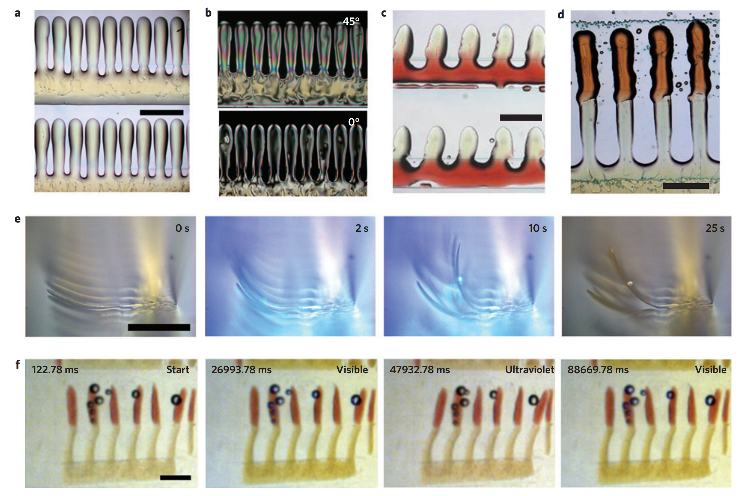
In this study, the light source used for generating Fig.7 was an Oriel 300 W broad-spectrum Hg(Xe) lamp and an EXFO Omnicure S2000 lamp. To select the desired wavelengths, filters used were necessary. An Andover 011FG09-50 filter to select ultraviolet wavelengths 280–390 nm, for the selection of the wavelengths 455 nm and up a Newport FSQ-GG455 filter is used. The intensities of light also play an important role in the stimulation. For the ultraviolet with the Andover filter, it is 9 \(mW/cm^2\), for the visible light with the Newport filter, it is 4 \(mW/cm^2\) and 20 \(mW/cm^2\) and 5 \(mW/cm^2\) for the ultraviolet and visible light without the filter, respectively.
Finally, the research group get a characterization of the response to light. It shows that A3MA and DR1A polymers can respond to different colour wavelengths of light, which verifies that the A3MA and DR1A polymers can be addressed independently and the actuators are possible.
Conclusion
Inkjet Printing Technology
One of the creative points of the new processing approach is using inkjet printing by photopolymerization. It is a material-conserving deposition technique, consisting of a solute dissolved in the solvent.\cite{singh2010inkjet} For many other micropatterning techniques, several steps of work are needed to vary the composition of the material on the substrate. The advantage of inkjet printing technology is that variation is easily achieved.
The inkjet printer is used for monomeric liquid crystal mix disposition. Due to the condition that only one single mix can be printed at one time, we use the approach that monomers are cured after printing every separate colour.
As what literature says, inkjet printing of actuators is an essential technology. It simplifies the method of processing on the microscale and provides the possibility for fast polymer microdevices fabrication.
Artificial Cilia Driven by Light
Another important point of this research is the artificial cilia produced by inkjet printing. It’s an imitation of the structure and behaviour of paramecia. To achieve asymmetric motion, A3MA and DR1A two dyes are used by varying the colour composition of the light. The mechanism is when the artificial cilia are illuminated by only ultraviolet light, only visible light, both ultraviolet light and visible light or no light, two dyes will transit into trans-cis isomerization and show flat and bent states.
In the experimental session, it shows that regarding the same intensity, the response of A3MA to ultraviolet light is much bigger than DR1A to visible light. By changing the different colours of the light, two dyes can be addressed independently, and the response is verified that is wavelength specific. Actuation with light successfully solves the problem of extreme driving conditions.